
I'm kind of a newbie having always worked with temporary HO layouts at Christmas but now I'm making a leap to N for a permanent layout with limited space.
I have a couple of questions, which are real basic type stuff, but it's driving me nuts and before I ruin something because of power connections I would like to get answers to these questions.
First, I saw where the turnout sections of track when using the power will direct the power down one path or the other but not both unless you set it up for no power controls. So, with one route being supplied electricity does that supply power to that entire segment of track to where I don't need to set up a power feed for it?
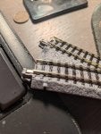
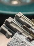
Second, I noticed the Kato turnouts come with an insulator block connected to the same rail for each route off of the turnout. This block is in the way when trying to make a clean connection between the two sections of track, so far without applying power to anything yet, just trying to work out the layout configuration for a smooth run, I have pressed down on that block to enable the sections to meet. IS THIS A BAD IDEA? without pressing this block down, I wind up with a gap in the connection. What am I doing wrong? and will this cause issues with the turnouts motor?
I haven't bought any turnouts, or track for that matter, in many, many years, and they were Atlas brand for HO. Technology has made some leaps since then and I'm not 100% sure I fully understand all of it yet
Thanks ahead of time for any help I can get on these very basic issues
Dave
with my old HO I would control the power by placing insulator connectors at a joint to control the power for different segments of track. and I can see where that can also be done with the Kato track as well, however when reading up on the Kato #4 and #6 turnouts they take care of controlling the power through the turnouts directional controls, I can see how this works but when the turnout is sending power down one rail will that take care of that entire segment of track?
I have a couple of questions, which are real basic type stuff, but it's driving me nuts and before I ruin something because of power connections I would like to get answers to these questions.
First, I saw where the turnout sections of track when using the power will direct the power down one path or the other but not both unless you set it up for no power controls. So, with one route being supplied electricity does that supply power to that entire segment of track to where I don't need to set up a power feed for it?
Second, I noticed the Kato turnouts come with an insulator block connected to the same rail for each route off of the turnout. This block is in the way when trying to make a clean connection between the two sections of track, so far without applying power to anything yet, just trying to work out the layout configuration for a smooth run, I have pressed down on that block to enable the sections to meet. IS THIS A BAD IDEA? without pressing this block down, I wind up with a gap in the connection. What am I doing wrong? and will this cause issues with the turnouts motor?
I haven't bought any turnouts, or track for that matter, in many, many years, and they were Atlas brand for HO. Technology has made some leaps since then and I'm not 100% sure I fully understand all of it yet
Thanks ahead of time for any help I can get on these very basic issues
Dave
with my old HO I would control the power by placing insulator connectors at a joint to control the power for different segments of track. and I can see where that can also be done with the Kato track as well, however when reading up on the Kato #4 and #6 turnouts they take care of controlling the power through the turnouts directional controls, I can see how this works but when the turnout is sending power down one rail will that take care of that entire segment of track?