Found your answer on the web
http://www.amhobby.com/download/man-tortoise.pdf
As T-Man suggested
From the web site
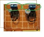
WIRING
Connections to the TORTOISE can be made by inserting light gauge wires through the holes in the printed circuit board. Solder the wires to
the pads using rosin core 60% tin, 40% lead solder (available from Radio Shack) and a small 25 - 35 watt pencil type soldering iron.
WARNING: DO NOT USE A HIGH WATTAGE SOLDERING GUN. DAMAGE TO THE PRINTED CIRCUIT BOARD IS NOT COVERED UNDER WARRANTY.
We recommend locating an 8 position terminal block near the TORTOISE and running the wires from the TORTOISE to it.
In this way, any
changes in wiring can be made at the terminal block without having to desolder connections on the board. A more costly option is to utilize a
10 position printed circuit board edge connector (available from electronics’ distributors - request Application Note AN-6000-04 for
specifications and ordering information from one mail-order distributor) which will simply plug onto the TORTOISE circuit board.
The connections on the circuit board are numbered 1 - 8 from left to right. Connections 1 and 8 go to the motor. 2, 3 and 4 connect to one
of the internal SPDT auxiliary switches which can be used to power the frog, signals, etc. In similar fashion, 5, 6 and 7 make up the other
SPDT switch. These auxiliary switches can switch a maximum of one (1) amp of current (they can safely carry 4 amps on each contact set)
and can switch either AC or DC loads. If you need to switch heavier currents, parallel both sets of contacts or you may connect a relay to the
output. Figure 2 shows the internal connections and switch configuration of the TORTOISE. (Request Application Note AN-6000-02 for
detailed wiring diagrams of turnout frog, relay and signal wiring.)